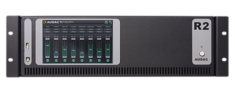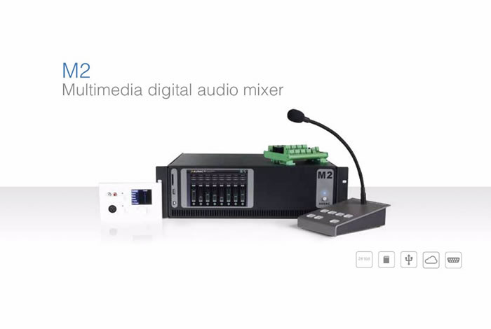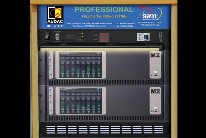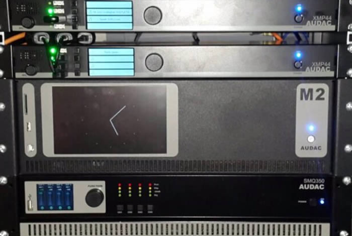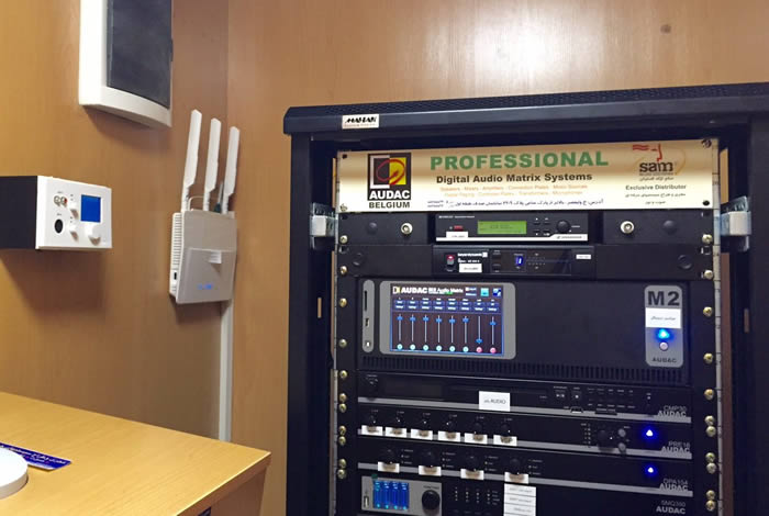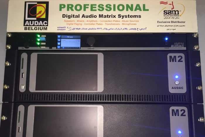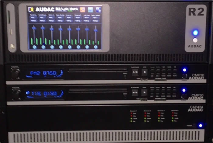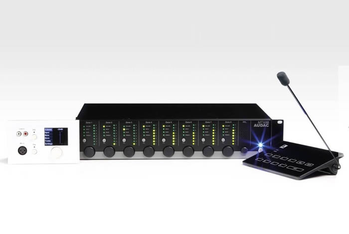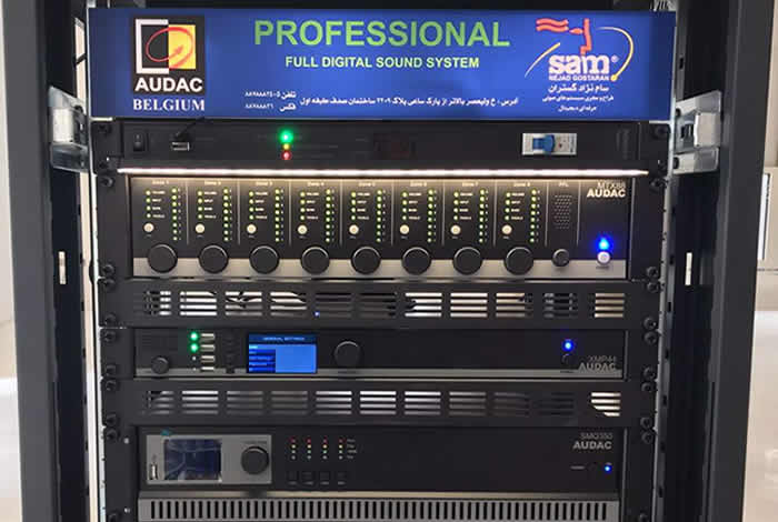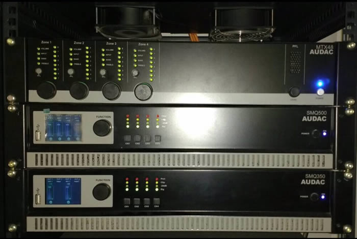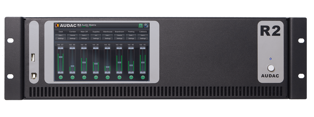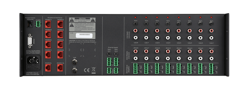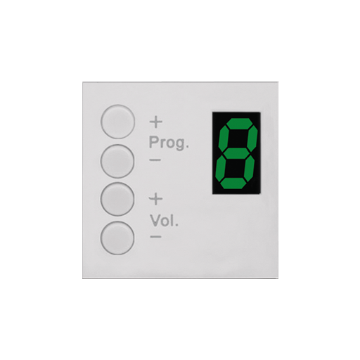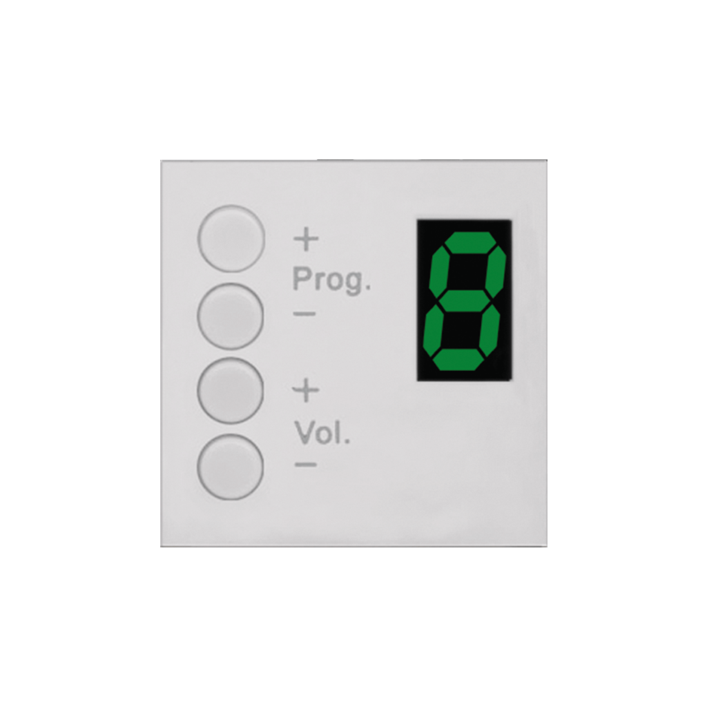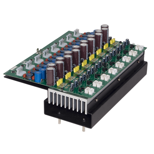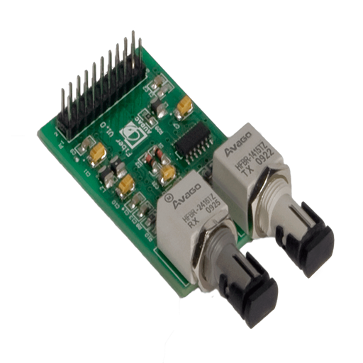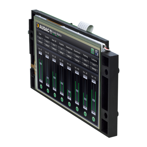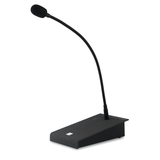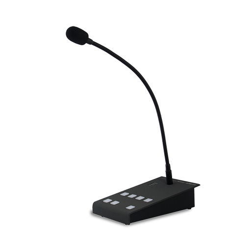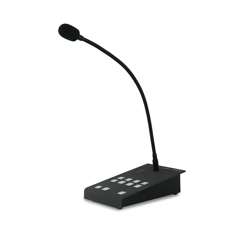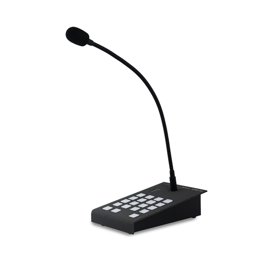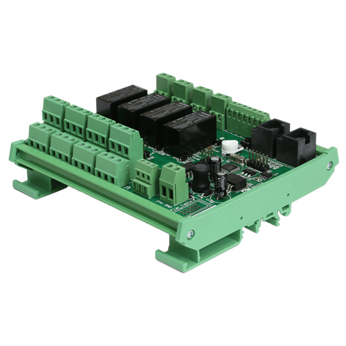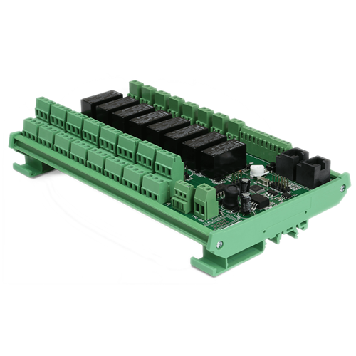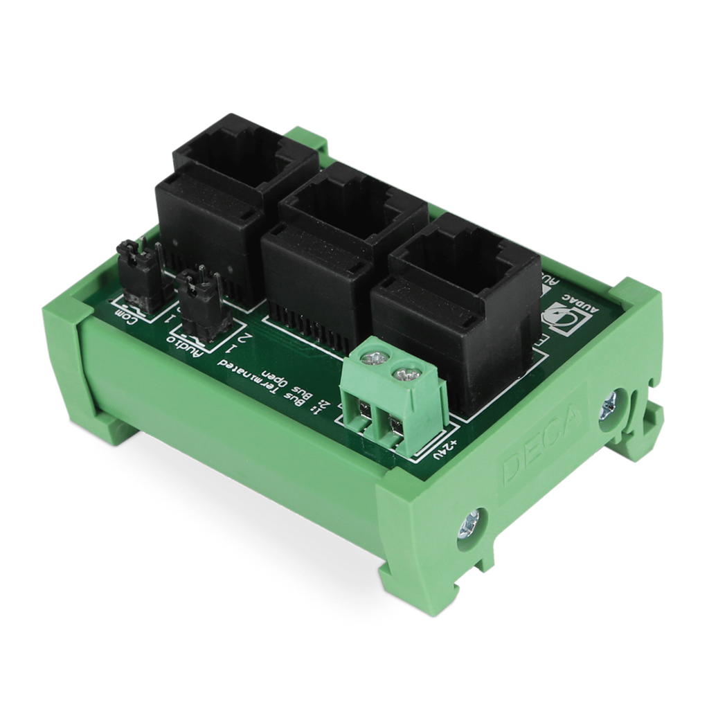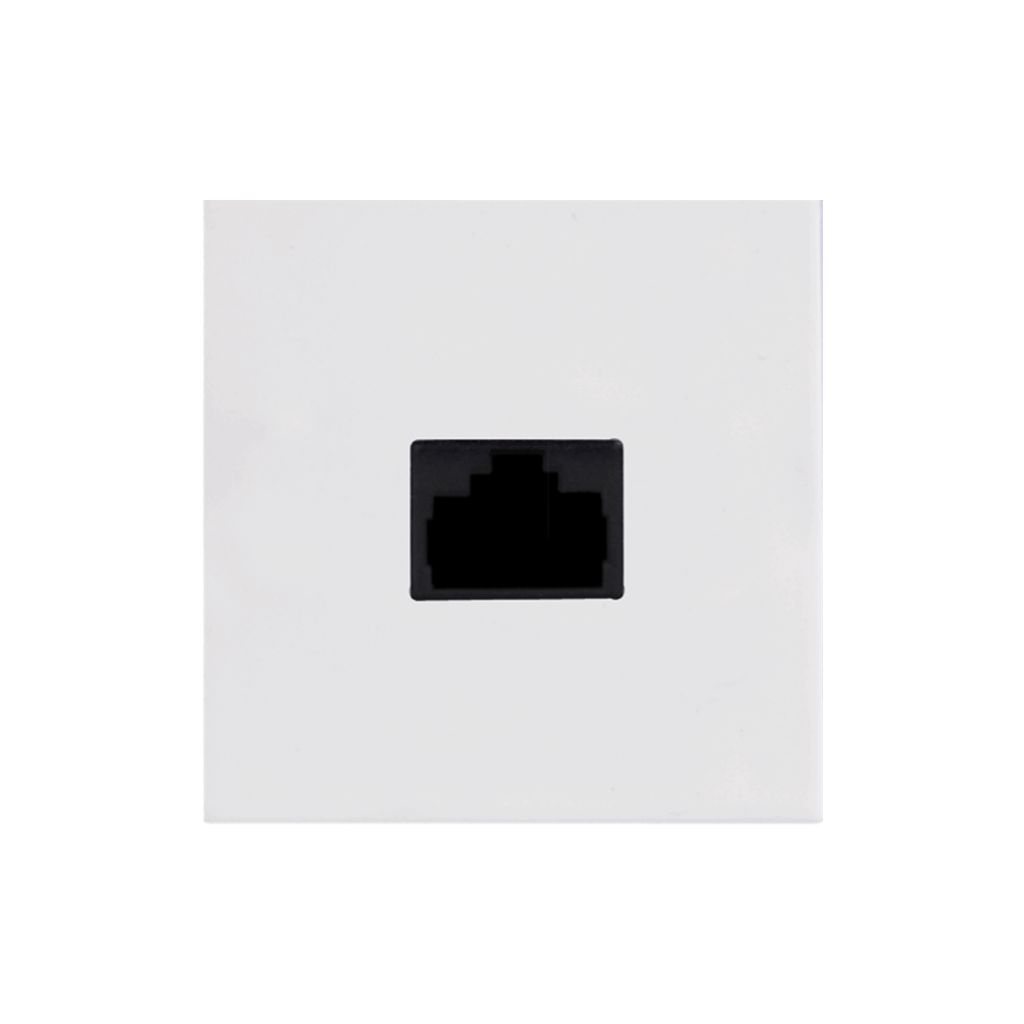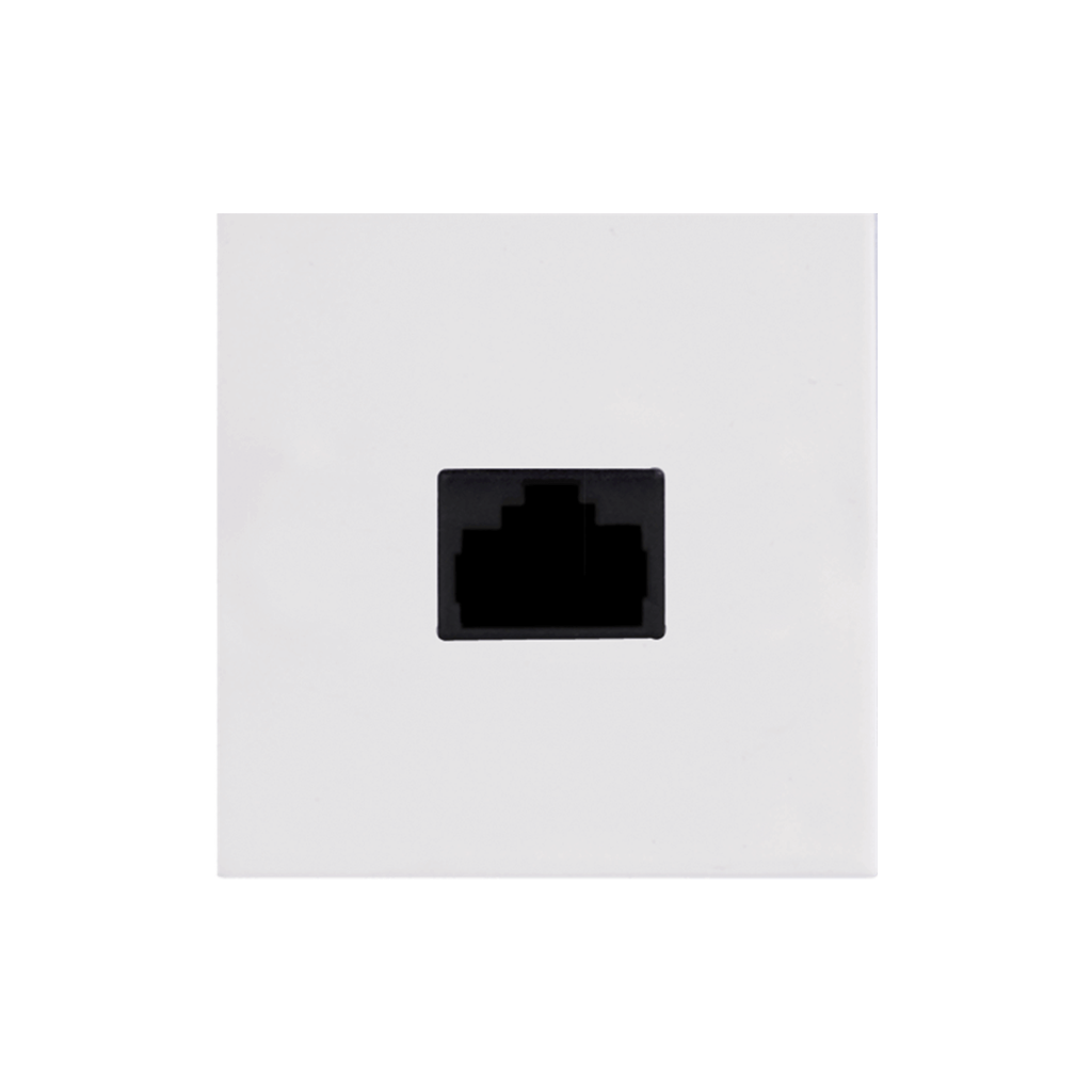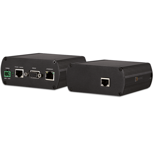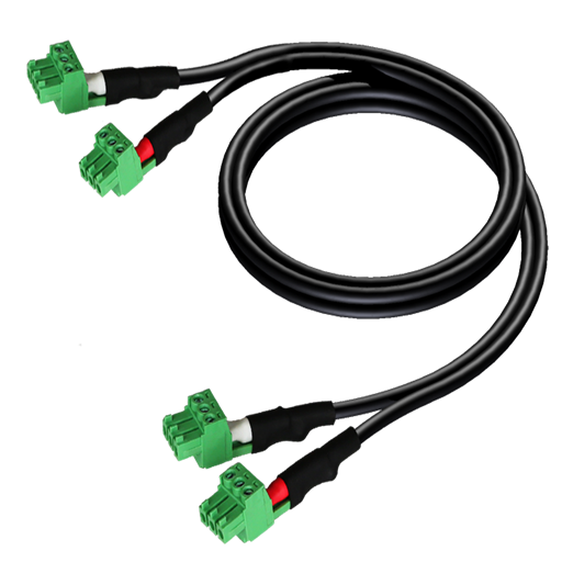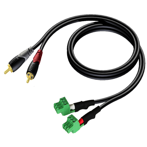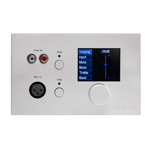
The R2 is a multi-zone audio distribution system which is a truly polyvalent solution for commercial and residential applications, with the flexibility of a multizone router. It delivers a comprehensive and expandable powerful solution for nearly every situation. With its large number of extension modules and configuration modes, it provides a solution for an uncountable amount of installations – large or small, simple or complex. In general, the R2 is an 8 x 8 digital audio matrix system, which is based on a powerful DSP processor. It is fully digitally controllable, and the built-in digital matrix makes it possible to patch any of the input signals to any of the output signals. The AUDAC APM paging tables are designed to create a powerful and flexible paging solution in combination with the R2. Note: The AUDAC R2DIS interactive 7″ touch-screen display kit shown on some promotional images of the R2 is an optional expansion kit not included in the standard R2.
PERIPHERAL DEVICE COMPATIBILITY TABLE
| SYSTEM SPECIFICATIONS | ||||
|---|---|---|---|---|
| Inputs | Balanced Mic./Line | Type | 8 x Balanced Stereo Input (Mic./Line) | |
| Connector | 3-pin Euro Terminal Block (Pitch – 3.81 mm) | |||
| Unbalanced Stereo | Type | 4 x Stereo Unbalanced Line | ||
| Connector | RCA | |||
| Balanced Priority Audio | Type | 2 x Balanced Priority Audio Input (Line) | ||
| Connector | 3-pin Euro Terminal Block (Pitch – 5.08 mm) | |||
| Peripheral Interface | Type | 10 x Peripheral Interface Input | ||
| Connector | RJ45 | |||
| Priority Contact | Type | 2 x Priority Contact Input | ||
| Connector | 2-pin Euro Terminal Block (Pitch – 5.08 mm) | |||
| Contact | Type | 8 x Contact Input | ||
| Connector | 9-pin Euro Terminal Block (Pitch – 5.08 mm) | |||
| Outputs | Balanced Stereo | Type | 8 x Balanced Stereo outputs | |
| Connector | 3-pin Euro Terminal Block (Pitch – 3.81 mm) | |||
| Power Amplifier | Type | 8 x Power Amplifier outputs (option) | ||
| Connector | 4-pin Euro Terminal Block (Pitch – 5.08 mm) | |||
| Relay | Type | 8 x Relay outputs (NO/NC) | ||
| Connector | 3-pin Euro Terminal Block (Pitch – 3.81 mm) | |||
| Control | Front panel (M2DIS Display option) | |||
| RS-232 | ||||
| TCP/IP (RJ45) | ||||
| Wall panel (RS-485) | ||||
| Audac Touch™ | ||||
| Web (HTML5) | ||||
| Web (Flash) | ||||
| Power | Supply | 100 ~ 240 V AC / 50 ~ 60 Hz | ||
PRODUCT FEATURES
| Dimensions | 482 x 132 x 350 mm (W x H x D) |
| Weight | 8.850 kg |
| Mounting | 19” Rack |
| Unit height | 3 HE |
| Optional expansion kit | M2DIS (7” Touchscreen display kit) |
| POW2 (Internal Power Amp 16 x 60 W) | |
| OPT2 (Fiber interconnection Interface) | |
| Peripheral Interfaces | DW5065 All-In-One Wall Panel |
| DW3020/4020 Wall control panel | |
| APM1xx Digital Paging Consoles |
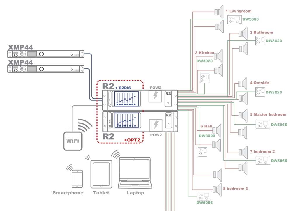
DOMESTIC SETUP EXAMPLE
The following figure shows an example of how an R2 could be used in a residential application. Sources such as a XMP44 Professional modular audio system are available. The M2 is controllable using one of the multiple wall panels or, wirelessly, through the Audac touch app or web interface.
Use the optional OPT2 kit the system can be easily expanded to include such zones as garage, basement and garden area.
INDUSTRIAL SETUP EXAMPLE
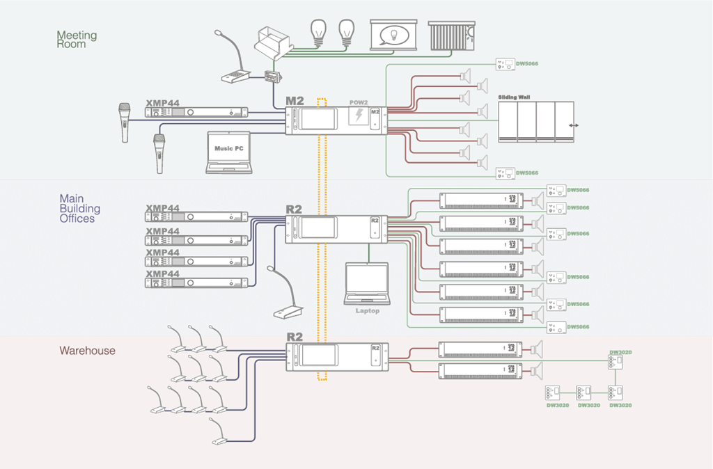
Below we can see an example setup using three matrix units in a medium-sized business.
First of all there is the main offices building with its own matrix, four XMP44 Professional modular audio system. Each zone in the building has its own local DW5066 wall panel for adjusting their zone settings according to their own preference or adding their own music sources to the system. A paging console is positioned near the front desk.
The warehouse has paging consoles setup across the building for easy communication between various parts of the supply and processing chain. Paging calls can be made globally or to specific departments. Local music choice and volume can be edited using DW3020 panels.
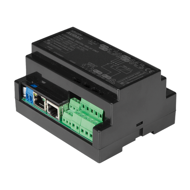
Finally the meeting room and its surrounding offices have a more advanced setup. Not only does the room have a powered M2 connected with two wall panels and a microphone, a paging console is also setup to control lighting, projection and window blinds using an ARJ and ARU relay system. Computers throughout the building allow authorised personnel to access the matrix unit’s advanced options.
FUNCTIONS
TIMER SCHEDULING
An internal real-time clock holds the actual time and date. This gives you the possibility to create specific time schedules. The actions that can be programmed are changing the routing of a signal, adjusting the volume of a zone, muting or editing the paging volume.
Single actions at a certain date and time or actions which repeat regularly (every day or week) can be programmed. A total of up to 256 timer presets can be made. For example, this can be useful when installed in a shop: the system turns on in the morning, turns off at night and remains off during the weekends.
PRIORITY INPUTS
Two audio priority inputs and two priority contact inputs are provided. Depending on the configuration, 4 priority signals can be used. The actions that need to happen when a priority signal occurs can be freely programmed. It can switch automatically to the priority audio inputs when an audio signal is applied or the internal routing can be adapted when a signal is available on the contact inputs. Each of the normal inputs can also act as priority inputs.
INTERNAL DSP SIGNAL GENERATOR
An internal DSP signal generator is provided which is able to produce sinusoidal signals with an adjustable frequency, white noise signals and pink noise signals.
ZONE LINKING
Two or more zones can be linked so that they use the same source, volume, etc. This linking can be automatically activated using priority contacts so that multiple zones become linked when, for instance, a separating wall is removed.
FREELY PROGRAMMABLE DSP FILTERS
It is possible to add a filter with freely selectable rollover frequency for up to 4 output channels. The rollover frequency is selectable between 10 Hz and 22 kHz and the filter response is selectable between a high pass filter, a low pass filter and a band pass filter. The filter settings can easily be made in the graphical user interface. When a subwoofer is connected, no more external crossover processor is needed.
WEB BASED USER INTERFACE
The R2 features a full functional web based user interface. This means that the amplifier can be fully operated by means of a web browser, which makes it possible to configure and control it from any device which is connected to the internet, such as a PC, Laptop, PDA or even a smartphone, without requiring additional software.
To access the functions of the R2, just use your standard web browser and surf to the IP adress that is configured in the R2 settings. After logging in with your personal username and password, you have full access to all functions of the R2 amplifier.
The web based user interface is very user friendly, and points out his own. After you have logged in on the website with your personal username and password, a fader overview of all output zones is displayed. The configuration menu gives an overview of all settings which can be made, such as time settings, network settings, priority settings, paging settings and the ability to bridge the outputs of the amplifier.
CONNECTIVITY

 REMOTE CONTROL & RS232
The main remote control input is an RJ45 connector which should be connected to a LAN network. This makes it possible to control the R2 system using a web browser.
The RS232 connector can be used to control the R2 with external controllers. This allows you to control the system using hardware from other manufacturers like home or industrial automation systems.
 PERIPHERAL INTERFACES
There are 10 RJ45 connectors provided for expansion with additional wall control panels and in- and output modules. All these connectors contain RS485 control signals so they allow you to control the amplifier from multiple locations. 8 of these connectors are capable of carrying bi-directional digital audio transfer signals for expansion of the input channels with additional wall line input units.
 LINK IN-AND OUTPUTS
An optional link in- and output allows connection of multiple matrix systems in cascade. This way, audio channels can be transmitted over fiber and installations can be extended over large distances (optional OPT2).
 PRIORITY INPUTS
There are two priority audio inputs provided, each with a gain control potentiometer. Furthermore, there are also two priority contact inputs provided.
 INPUT 1-8 / OUTPUT 1-8
8 line level in- and outputs are provided. Each audio input channel has a clipping LED which indicates when the input signal is distorted, a gain control potentiometer to control the level of the input signal and RCA input connectors.
Each zone output is standard fitted with an RCA line level output connector for the connection of external amplifiers. When the optional power amplifier kit is installed, each zone has an amplified stereo audio output with a power of 2 x 60W at 4Ω.
R2 REMOTE FOR IPHONE, IPAD & IPOD TOUCH

-
WHAT ADDITIONAL FUNCTIONALITY DOES THE M2 HAVE OVER THE R2?
Inputs Automatic Level Control (ALC):
The inputs of the M2 can accept both Line and Microphone Level signals. (The R2 can only handle Line level signals) The gain of the inputs can be adjusted manually through the web interface, but can also be adjusted automatically by the internal ALC (Automatic Level Control). The ALC will keep your inputs on a constant level.Noise Gate:
The inputs of the M2 have a noise gate (which can be enabled by software). This noise gate will mute the inputs automatically when the level is below a certain level. This can be useful to eliminate unwanted noise, hum or background noise when a microphone is connected which isn’t being used at a certain moment.Mic/Line pre-sets:
Because of the many input settings and possibilities, a preset for mic and a preset for line sources is implemented. These presets will enable the ALC and noise gate with the correct settings. A high pass input filter will also be enabled when the mic preset is chosen. These presets can always be overruled by manual settings.Mono/Stereo:
A mono-stereo selection switch will be enabled on the inputs. This should be used when for example a Mono microphone is connected. When the mono switch is enabled, the signal applied on the left channel will be copied to the right channel.3/5 band EQ:
Each input contains a Three or Five (selectable) parametric EQ to adjust the input signal. The frequencies, levels and bandwidth are adjustable.48V Phantom:
Every input contains the possibility to enable 48 Volt phantom power, for powering condenser microphones. This phantom power can be enabled in the software.Outputs
Delay:
A delay can be enabled on all the outputs of the M2. The delay is selectable between 0 ms and 2000 ms.Mono/Stereo on outputs:
Mono / Stereo switching can be done on all the outputs of the M2. When switched to Mono, the left and right channels will be mixed to one signal and are available on both left & right output channels.Max Volume:
The maximum output volume can be selected. This way, a limiter will be applied to the outputs, making sure that the volume can’t exceed a certain volume level.5 band EQ on outputs:
Each output will have a 5-band parametric EQ whereby the signal can be adjusted to the acoustics of the room. The frequencies, bandwidth and level of the EQ are adjustable. In addition to the 5-Band EQ, there is still the two band tone control on the outputs.Output Filter:
A digital filter can be applied to the M2 outputs. This filter can be selected between Low Pass, Bandpass and High Pass. The M2 has much more DSP power than the R2, which makes it possible to apply a digital filter to all outputs simultaneously.Mixing:
Multiple input channels can be mixed to one output.Output scenes:
Up to 8 preset mixing scenes can be made for one output (Total of 64 preset mixing scenes for one M2). Mixing scenarios can be predefined in this way, to create one preset for every possible situation, setting the mixing levels for all inputs to the desired level by only one action. The mixing scenes can be recalled by manual operation, pre-defined timer events, contact input, wall panel, …Relay (NO/NC):
Every channel contains a relay output with both NO and NC contacts. These can be triggered by contact, pre-defined timer events, paging call, etc. and can be used to control all different kinds of external devices. Some examples are overruling of manual 100 Volt volume controllers (24 Volt), enabling of emergency lights, …Global
Global scenes:
Besides the mixing scenes which can be made for every output separately, also some global mixing scenes can be programmed. By using the global mixing scenes, the mixing levels for ALL outputs can be set by only one action.Talk over:
For every output, one talk over channel can be assigned. This input will be automatically mixed with the current signal of the output channel. The talk over level and the level of the current signal of the output channel can be defined. This makes it possible to automatically reduce the level of the current signal available on the output channel.Auto mixing:
Auto mixing will allow you to automatically mix predefined inputs together and prevents the output volume to become too high. The mixing levels will be adjusted automatically depending of the triggered inputs.Contact inputs:
The contact inputs can be used to trigger priorities, voice-file messages, output linking and scenes. Extra features can be implemented in the future. -
WHERE CAN I FIND THE LATEST SOFTWARE VERSIONS?
Any product that is updatable by the AUDAC system manager is automatically discovered and downloaded to your personal computer.
All other software versions can be found via audac.eu/software
-
DO I NEED TO UPDATE MY DEVICE?
No, this is not always needed. When downloading the latest software, it will also include a text file containing the patch notes. If you are not having issues with your current software or do not need the added functions, then you do not need to update the product.
-
HOW CAN I RESET MY AUDAC PRODUCT PASSWORD?
When the user password is lost, it can be changed by logging in with the administrator password. When the administrator password is lost, please contact your local distributor. They will be able to reset your password by using the web-browser interface.
-
WHAT DO I NEED TO DO WHEN THE WEB INTERFACE IS SHOWING ‘SOCKET CONNECTION FAILED’?
When ‘Socked connection failed’ shows up on the web interface, it means your browser was able to load the website from your AUDAC product, but that the connection which has been established between your computer and the AUDAC product to send the commands is blocked by something in your LAN network. Check the following :
- Check if any Firewall is blocking port 5001 and port 843 in your network.
- Delete browser history and refresh webpage.
- Reset AUDAC product
If you have the current settings, reset the product and try again.
-
HOW DO I FIND OUT THE IP ADDRESS OF THE AUDAC PRODUCT IN MY NETWORK?
Please download the AUDAC system manger. This will scan your network and tell you the IP address of all AUDAC products within your network.
If your network is blocking global broadcasts, you can connect directly by using a cross cable. The system manager will still be able to inform you of the device IP.
-
HOW CAN I UPDATE MY PRODUCTS?
AUDAC uses two methods to update their devices.
- USB
- AUDAC system manger
When unsure which method to use, please refer the product manual.
-
I CANNOT CONNECT TO MY AUDAC PRODUCT. WHAT SHOULD I DO?
When connecting directly to the product,
- Ensure you are using a cross-link network cable
- Ensure your personal computer is within the same default AUDAC IP range 192.168.0.xxx
- Check the WIFI settings of your laptop. In many cases, the laptop will try to make a priority connection through the WIFI network, whereby it will be impossible to reach the webserver. After the WIFI connection of the laptop is disabled, it will work properly
When connecting to your product via network
- Ensure your personal computer is within the same default AUDAC IP range 192.168.0.xxx
When trying to connect with a personal media device.
- Ensure the tablet/pad is within range of both the WiFi and AUDAC IP range.
-
IS IT POSSIBLE TO PLACE MULTIPLE CONNECTED UNITS IN SEPARATE BUILDINGS, SUCH AS MULTIPLE BUILDING BLOCKS FOR A FACTORY? HOW CAN THESE UNITS BE CONTROLLED?
It is possible to place different R2 and M2 units on different locations in separate buildings. This solution can be useful when the audio system from a factory should be linked between different production plants and/or office buildings.
The control of these matrix systems (multiple linked with each other) can be done through the web-based user interface on two different ways.- Connect each individual matrix systems to a LAN network, while assigning each of them a unique IP address. The access to the matrix can be achieved by connecting to every matrix its unique IP address.
- Connect ONE of the linked matrix systems to a LAN network, while others are only connected through the fiber interconnection. The access to the matrix systems (all of them) can be done through the IP address of the matrix connected to the LAN network. Control for other linked matrix systems can be done by selecting the address of the desired matrix system in the web-based user interface, and data intended for other linked matrix systems will be transferred over the fiber interconnection.
-
HOW MANY WALL PANELS CAN BE CONNECTED TO EVERY UNIT?
This depends of the kind of wall panel you are using.
- Wall panels with control and audio inputs : one wall panel per RJ45 input.
- Audio only wall panels : two per RJ45 input.
- Control only wall panels : these can be linked together in combination with all other AUDAC wall panels
Please refer to the product manuals for the detail connection possibilities for each matrix.
-
CAN THE RS232 PORT BE CONTROLLED BY AMX OR CRESTRON UNITS?
Yes, the RS232 can be controlled by any device supporting RS232. Some examples are: a computer, home and industrial automation systems like AMX and Crestron. The command set for controlling the devices over RS232 is downloadable here.

